Tutorial: first project in 5 minutes
This tutorial walks you through a simple project to get started: a basic cabinet in 19 mm white melamine. By the end you’ll have a complete cutting layout and a PDF ready to print for the workshop.
Allow about 5 minutes.
What we’re building
Section titled “What we’re building”We’ll make a standard cabinet, outside dimensions 800 × 600 × 580 mm (height × width × depth), with:
- 2 vertical sides
- 1 top
- 1 bottom
- 1 back in 19 mm panel (for this example we simplify: no thin back)
- 1 adjustable shelf
- 1 door
That’s 7 parts in total.
Step 1 — Set up the material
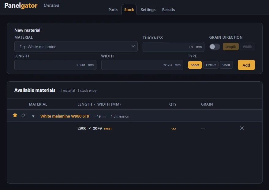
Section titled “Step 1 — Set up the material”Before entering the parts, we need to declare the panel we have on hand. Click the Stock tab (or Ctrl+2).
Create the material
Section titled “Create the material”In the New material form at the top, enter:
- Material:
White melamine W980 ST9 - Thickness:
19mm - Length:
2800mm - Width:
2070mm - Type: select
Full sheet - Click Add
Step 2 — Create the “Cabinet 1” group and enter the first part
Section titled “Step 2 — Create the “Cabinet 1” group and enter the first part”Switch to the Parts tab (Ctrl+1).
In the New part form at the top, enter:
- Group:
Cabinet 1— the new group is created and the Group dimensions fields appear (optional). - Group dimensions: Height
800mm, Width600mm, Depth580mm - Label:
Side - Length:
800mm - Width:
580mm - Quantity:
2 - Edge banding: add the front edge by clicking the length
800— the active edge appears in gold - Material: select
White melamine W980 ST9 — 19 mm - Click Add
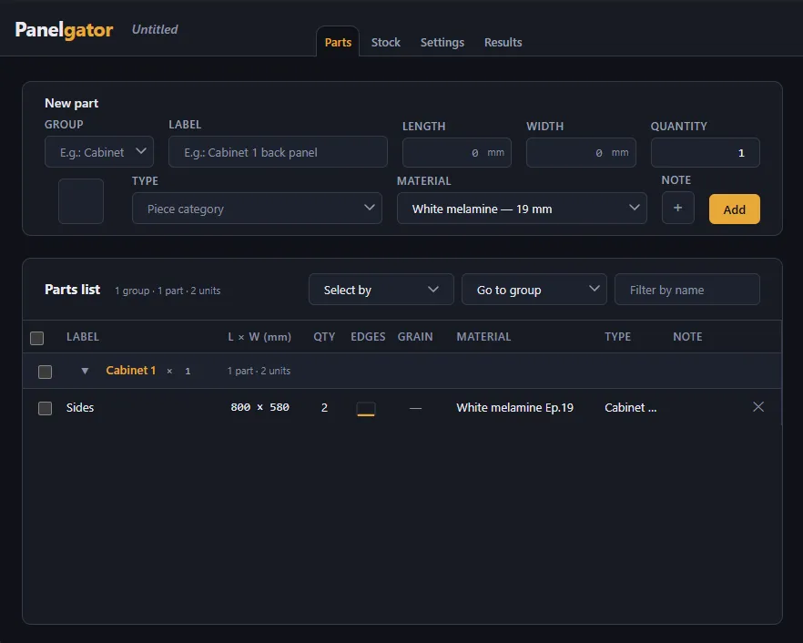
The group now appears in the parts list and contains our two sides.
Step 3 — Enter all the parts
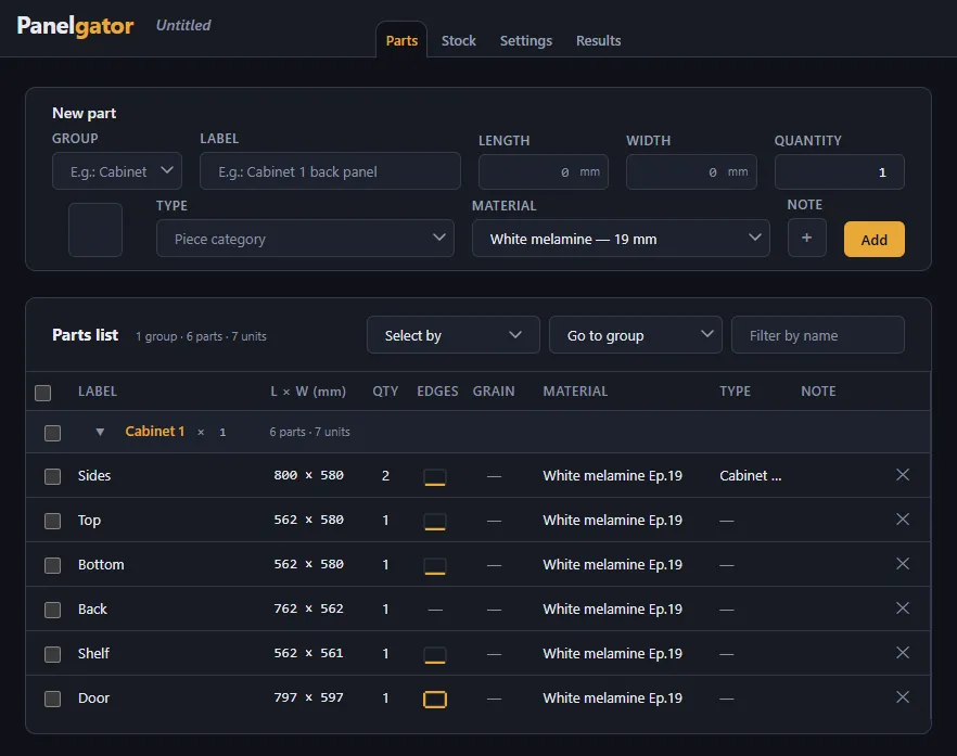
Section titled “Step 3 — Enter all the parts”Add the remaining parts from the New part form. The Group selector stays on the last group created, so you can chain entries faster.
| Label | Length | Width | Quantity | Edge | Material |
|---|---|---|---|---|---|
| Top | 562 | 580 | 1 | front | White melamine 19 mm |
| Bottom | 562 | 580 | 1 | front | White melamine 19 mm |
| Back | 762 | 562 | 1 | — | White melamine 19 mm |
| Shelf | 562 | 561 | 1 | front | White melamine 19 mm |
| Door | 797 | 597 | 1 | all | White melamine 19 mm |
Step 4 — Check the settings
Section titled “Step 4 — Check the settings”Click Settings (Ctrl+3).
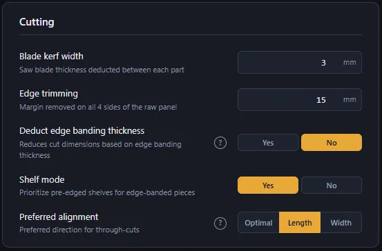
For this first project:
- Preferred alignment: Length
- Saw kerf:
4mm (typical for a workshop circular saw) - Squaring allowance:
15mm on 4 sides of full sheets
You can adjust these values later based on your equipment and habits.
Step 5 — Run the cutting layout
Section titled “Step 5 — Run the cutting layout”Switch to the Results tab (Ctrl+4), then click the Compute button at the top right.
Step 6 — View the results
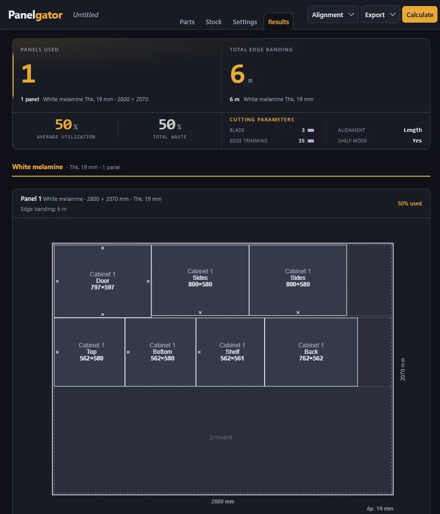
Section titled “Step 6 — View the results”You’ll find at the top:
- The number of panels used
- The edge banding lengths used
- The utilization and drop percentages
- A reminder of the cut parameters
And below, the cutting plan for the panel:
Each part in the cutting plan shows its group, label, dimensions (length × width), and banded edges marked with X.
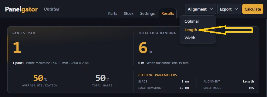
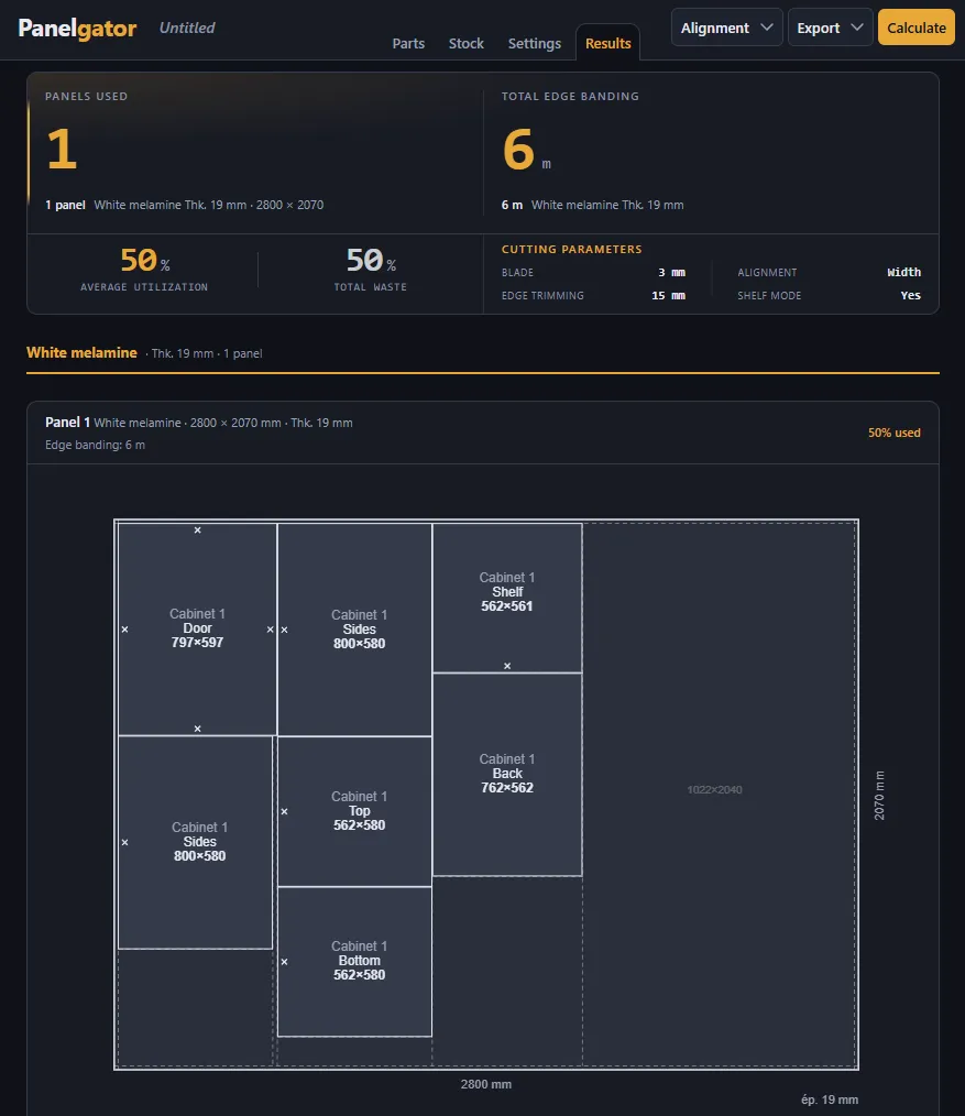
You can change the alignment preference via the Alignment menu at the top right. Select Width — the plan is reorganized without a new computation.
Step 7 — Export to PDF
Section titled “Step 7 — Export to PDF”This is the document you’ll take to the workshop.
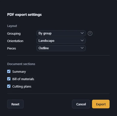
- Still in the Results tab, open the Export menu then choose PDF
- A modal opens with the page layout options
- Keep the default values for our example (all options detailed in PDF Export)
- Click Export
- Pick a save location
Step 8 — Save the project
Section titled “Step 8 — Save the project”Ctrl+S, or File > Save As, to save the project as a .pnlg file. Pick a name (for example tutorial.pnlg) and a location.
You can reopen this project anytime to edit it.
What’s next?
Section titled “What’s next?”Great, you’ve toured the essential features. To go further:
- Import a parts list — see BXF2 Import or CSV Import
- Set grain direction and edges on decorative melamine — see Grain direction and edges
- Understand advanced settings (edged-board mode, edge thickness compensation) — see Settings tab
- Export to DXF for digital workshops — see DXF Export
Happy cutting!